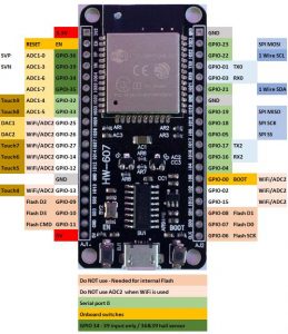
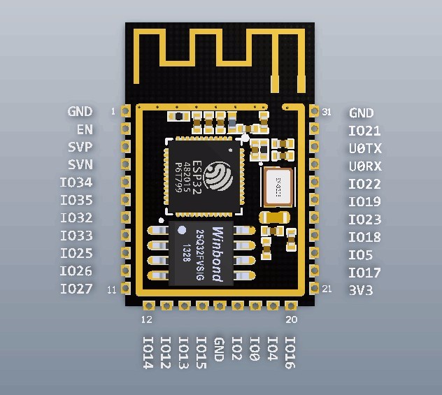
Not all pins of the ESP32 can be used.
Below a list of all special pins of the ESP32
- The application can use ADC2 only when Wi-Fi driver is not
 started, since the ADC is also used by the Wi-Fi driver, which has higher priority. GPIOs 0, 2, 4, 12 – 15 and 25 – 27
 - Some of the ADC2 pins are used as strapping pins (GPIO 0, 2, 15), so they cannot be used freely.
- ESP32 Core Board V2 / ESP32 DevKitC: GPIO 0 cannot be used due to external auto program circuits.
- ESP-WROVER-KIT V3: GPIO 0, 2, 4 and 15 cannot be used due to external connections for different purposes.
- The hall sensor is internal to ESP32, reading from it uses channels 0 and 3 of ADC1 (GPIO 36 and 39). Do not connect anything else to these pins and do not change their configuration. Otherwise it may affect the measurement of low value signal from the sensor.
- Pins 34-39 are input only
- GPIO 6-11 are used for the flash, so you can not use them.
- Serial0 is on GPIO 1 & 3 (TX RX). Serial2 on on GPIO 17 & 16 (TX RX)
Serial1 is per default on GPIO 9 & 10, but they are used for Flash.
You can modify Arduino\hardware\espressif\esp32\cores\esp32\HardwareSerial.cpp to assing different GPIO pins. - I2C pins: 21 = SDA & 22 = SCL
- Pins 2, 4, 5, 12, 13,14,15 support internal pull up/down.
- Pins 25, 26, 27 supports internal pull-up.
if(_uart_nr == 1 && rxPin < 0 && txPin < 0) {
        rxPin = 9;
        txPin = 10;
    }

