
Measure CO2 with MQ-135 and Arduino
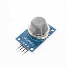
I had bought 3 MQ-135 gas sensors on AliExpress to test if it is possible to measure CO2 with them.
First I started with a very simple analog read to check the values in my computer/hobby room with a CO2 ppm around 650.
// select the input pin for the MQ-135 sensor
int sensorPin = A6;
// variable to store the value coming from the sensor.
int val = 0;

void setup() {
  Serial.begin(9600);
}
void loop() {
  // read the value from the sensor
  val = analogRead(sensorPin);
  Serial.println (val);
  delay(1000);
}
24 hours Burn-In
I connected the 5V power to the sensors and let them alone for 24 hours to burn in.
After these 24 hours I checked the values measured with the above little test program.
The values were 13 – 32 – 55
Breathing on them gave very little difference, as the values were only doubled to 28 – 61 – 103
With these values you can say that the first two are useless to measure CO2 as the difference is to little.
13 – 28 for CO2 ppm of about 500 – 2000 gives a resolution of about 100ppm/value measurement
32 – 61 gives about 52ppm/value
55 – 103 gives the best resolution of about 31ppm/value
These resolutions are valid if the scale is lineair, but the scale is logirithmic.
So in the lower ppm part the resolution is much better, but above the 1000ppm the resolution will be very low.
Wrong hardware
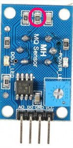
Found out that the resistor towards ground was just 1K ohm, after replacing the resister with one 22K ohm the results were getting much better.
In my room s the real ppm was about 770 ppm according to my NETATMO.
The raw value measured with the arduino was now 241.
Using MQ135-master from G.Krocker site and modifying MQ135.h with the correct RLOAD resistor value of 22K and a RZERO of 879.13
and using the below Arduino code
// The load resistance on the board
#define RLOAD 22.0
// Calibration resistance at atmospheric CO2 level
#define RZERO 879.13
#include "MQ135.h"
MQ135 gasSensor = MQ135(A6);
int val;
int sensorPin = A6;
int sensorValue = 0;
void setup() {
  Serial.begin(9600);
  pinMode(sensorPin, INPUT);
}

void loop() {
  val = analogRead(A6);
  Serial.print ("raw = ");
  Serial.println (val);
  float zero = gasSensor.getRZero();
  Serial.print ("rzero: ");
  Serial.println (zero);
  float ppm = gasSensor.getPPM();
  Serial.print ("ppm: ");
  Serial.println (ppm);
  delay(5000);
}
The Arduino sends out the following output to the serial port.
raw = 241
rzero: 691.60
ppm: 777.87
With these values I am very close to the values of the NETATMO
I will of course also run the calibration outside where it should show about 400ppm, and eventually adjust the RZERO in MQ135.h
Next day
The next morning ppm was down to 500 according to the NETATMO, but the arduino showed a ppm of 600. I change the RZERO to 819 and the arduino also showed 500.
This is no good of course, so something must go wrong in the calculations in the MQ135 library. Or I am using a MQ-135 sensor with a bad response curve.
The next day I have tested the same with another MQ-135, but the results were about the same.
Wrong formula in the MQ135.h library
The formula to calculate the resistance of the sensor is wrong.
It should read:
float MQ135::getResistance() {
  int val = analogRead(_pin);
  return ((1023. / (float)val) - 1.) * RLOAD;
}
MQ135 not suitable for CO2
I think that I will stop my attempts for using the MQ-135 as a CO2 meter. With 1 sensor I measured different voltages on the analog port with same amount of CO2. It probably is to responsive to other gases in my surroundings. (Airport and highway).
One evening while my wife was one floor lower and took some perfume the ppm went sky high from 640ppm to 5570ppm, and then slowly (30 minutes) went down again.
I think that I will connect it to an ESP8266E to measure the outside air quality and sent the data over WiFi to thingspeak.com .

Looks awesome. Can’t wait to see the results!
Hi
Great workout, even i am having same problem. I am from india Bangalore, and my area CO2 level is 390 ppm but my mq135 show not even near to it. I am using same library, and i am getting 0.5 ppm. I also tried, with externally soldering 22k resistor in between A0 and gnd. But nothing change.
Please help me
Thank you
Suman
Hi Suman,
Did you remove the wrong 1K resistor?
or
change:
#define RLOAD 22.0
to
#define RLOAD 1.0
When changing the value of RLOAD to 1.0 you do not need the 22K resistor.
and you also need to change the formula in the library.
Regards,
Rob.
use TGS4161 if you want to measure CO2
the sensor needs around 24-48 hours to “burn in” als0 you are able to calibrate it with the screw on the back
https://c.76.my/Malaysia/mq-135-air-quality-detector-sensor-module-arduino-iot-littlecraft-1611-20-littlecraft@7.jpg
Hi Remco,
24 hours should be enough for the burn-in.
The screw on the back is only to adjust the on/off point of the digital output. It does nothing to the analogue output.
Regards,
Rob.
hi there,
i was run that program but i get a error message like that “‘gasSensor’ was not declared in this scope” and error in this line of code please help me to solve this float ppm = gasSensor.getPPM();
Hi Hari,
I just noticed that the following was on 1 line in my example:
#include “MQ135.h”
MQ135 gasSensor = MQ135(A6);
It should be like the above on 2 seperate lines.
Regards,
Rob.
Hi ! I have a couple questions concerning your tweaks !
I have a similar MQ135 board (the PCB and resistor values seem to be the same) and the sensor doesn’t seem to be sensitive to anything (the analog output doesn’t seem to change when exposed to C02, lighter gas, alcohol or smoke). I’m wondering if it could be due to one of the following:
-The stock load resistor is too small.
-My arduino uno 5V pin can’t provide enough power for the MQ135.
Do you have any why I am not getting any meaningful reading from it?
Regards,
Jocelyn.
Hi,
You really need to change the resistor to get some variance in the output.
The 5V pin on the arduino comes directly from your USB port power.
Regards,
Rob.
Hi sir, so float MQ135::getResistance() {
int val = analogRead(_pin);
return ((1023. / (float)val) – 1.) * RLOAD;
}
meaning that the equation should be changed to this instead of 5-1? And may i know how to set the RO since every-time the value is varies.
Ho Aron,
Yes, that is correct.
I also had problems with R0.
The MQ-135 sensor is to sensible for other gasses in the air so that is not possible to get good values for CO2 from it.
Regards,
Rob.
Dear Mr Rob, I am working on a project which uses MQ 135 sensor board. I see that my RL is 1K ohm. Can I use the blue colour preset, which is provided in the board to change value of RL to 22K?. Kindly suggest? Or can I retain the same 1K, and just change the # define and alter the MQ 135 library.h . Actually I am using it for the first time. I have not yet calibrated still by burning it for 24 hours. I just wanted to have an initial check.
Without changing the formula it was reading 0.5 to 0.4 ppm, and now after changing the formula, as suggested by you, ppm is in the range of 36 to 38. Still I am far away then the usual range of 600 to 700 ppm.
Hi Aravind,
It is best to replace the 1K resistor with a 22K resistor.
With the 1K resistor the readings are not sensitive and just changing a little bit while the CO2 is changing a lot
Regards,
Rob.
Hey Rob, thank you for the explanation. I’ve got a couple of noob questions that are a bit long. I would really appreciate if you took a look at them when you have time. Thanks a lot in advance.
I have this model (see link 1 below), how do I know the RLOAD value of this model? I currently use 10.0 as RLOAD, because that’s what the library I use came with (I am using the library in link 2 below, is that a good one?). Do I need to change the RLOAD value? If I do, then (1) do I have to change anything in the .h file and (2) do I need to recalibrate? I have been calibrating for the past 48 hours.
I was also wondering, what exactly is Rzero? Specifically, why can’t we (instead of defining it as a fixed value), continuously retrieve the value of getRZero() or getCorrectedRZero() in real time, and use that retrieved value in the PPM calculations. Is it because, if the Rzero is not constant over time, is that indicative of a problem in the hardware/calibration? If, after calibration, I get a constant Rzero in my living room, do I need to recalibrate and edit the Rzero value when I move the sensor to my bedroom? Or am I misunderstanding the issue completely? Finally, I calculate the PPM value by averaging retrieved values over 30 seconds, with 2 measurements per second. Are these numbers OK, or are the optimal numbers different (e.g. averaging over 10 seconds with 1 measurement per second , or some other combination)?
Thank you again for any clarification, and all the best.
Link 1: https://www.amazon.com/gp/product/B00LSG5IZ2/
Link 2: https://github.com/ViliusKraujutis/MQ135
Hi Uygar,
The last picture on Amazon shows that RLOAD is 1K (it has text 102 on it)
It is on the same place as my example.
You only need to change line 25 (RLOAD) in the .h file to adjust the value.
But it will be better to use a 22K resistor, as the readings above 1000ppm will be much more accurate.
The formula in the .cpp file is correct in this library.
The Rzero only needs to be done once outside in as much as possible clean air.
This will calibrate the sensor with the reference of 397.13ppm (ATMOCO2 line 42 .h file)
I think it will better to change that value to 403, as 397 was the lowest CO2 a few years ago.
Lowest CO2 now a days will be 403 in the forests, if you live in a city with high car pollution your lowest CO2 will be around 410-425
Your average calculations are good. The more measurement you take the better it will be.
Regards,
Rob.
Thanks so much for the prompt and detailed response. Just a quick follow up, where exactly do I put the 22K resistor? Do I need to remove the on-board resistor and replace it with a 22K one (and I don’t have the means to do that), or can I use breadboard to just add a 22K resistor? In that case, where do I put it in the breadboard? Will resistance add up to 23K if I do that? As you can probably tell, I have near zero hardware experience, so I want to thank you again for taking the time to explain.
Hi Uygar,
You can see the red circle on the picture where I mention that the resistor is wrong.
That tiny resistor needs to be removed, and then a new 22K resistor needs to be added on the same place.
I used a normal resistor and soldered it to the board. It is not an easy job, but can be done with the correct equipment.
If you have no experience with soldering you better leave the 1K resistor and change the value in the library.
Regards,
Rob.
Will it work if I don’t make the changes in the resistor? If not what changes do I have make in the Library?
Thanks for your effort.
You only need to change line 25 (RLOAD) in the .h file to adjust the value.
But it will be better to use a 22K resistor, as the readings above 1000ppm will be much more accurate.
And one more thing Sir, please say what I exactly have to do after I have done the 24h burnout. And also say how to find the RZERO
and what changes I have to do. Please don’t mind because I don’t have any idea how to do it.
Thanks a lot
The Rzero only needs to be done once outside in as much as possible clean air.
This will calibrate the sensor with the reference of 397.13ppm (ATMOCO2 line 42 .h file)
I think it will better to change that value to 403, as 397 was the lowest CO2 a few years ago.
Lowest CO2 now a days will be 403 in the forests, if you live in a city with high car pollution your lowest CO2 will be around 410-425
In burnin in the sensor does it need to upload code or just connect it to the power source?
yes, just connecting it to the power will do.
Is their any calibration techniques to detect benzene using mq 135???
Sorry, I do not know.
Hey everyone, once we have applied 5v for more than 24 hours in second time how much time we should wait for good result???
After a 24 hour burn-in you can directly do the calibration.
If you had to power it down after the burn-in then calibration can be done after 1 hour power-on.
Hi Rob!
Can I ask, if the voltage is 3.3 V, do I need to modify the library somwhere?
Thanks!
You need 5V to heat the MQ135
Hey rob,
I just have a noob question, After i have burned it for 24 hrs…How I will get the RZero value?? I mean what is the code for getting the RZero after the burnout?
Please explain this i have searched many blogs and articles for this.
Thank you
Thanks for the excellent writeup. Also thanks for patiently answering all of the questions you receive. Myself, I stopped publishing articles like this, because people don’t do their own research, and I had to answer the same simple questions over and over. Again, thanks for your knowledge and patience.
Hi Rob,
this has been inactive for a while. But who knows, maybe you’re still there.
I was just wondering how the corrected R0 which takes temperature and humidity into account fits in here.
Shouldn’t the corrected outside value read 400ppm?
As per my understanding, if i calibrate to R0 (w/o temperature and humidity) it will give different values depending on whether I do it in summer or winter.
Any thoughts on this?
Best regards,
Nils
If your temperature and humidity changes the ppm to much between summer and winter then your extra calculations are wrong.
As the MQ135 is heated the outside temperature/humidity does not give very high variation.
Also take care that your temperature sensor is not to close to the MQ135
rob now i need to print these ppm values to my 16×2 LCD display with i2c module give me another code with lcd.print
Just change the Serial.print statements with lcd.print.
Look on other sites how to connect the LCD to your board
Friends
I had been reading about MQ135 for quite some time, running the guidelines here and other sites, but the results were a tragedy.
I opened the library and saw that it used parameters t and h (temperature and humidity) in the calculations and in the examples presented they were not transferred.
I disassembled the library and brought the formulas to the arduino IDE and included the library to read a DHT sensor.
Solved the problem, I calculate the Rzero and calculate the CO2 in ppm.
With t=13.10ºC and h=71.20%, I am getting 430ppm indoors.
I didn’t do the Rload substitution from 1K to 22K.
I still want to compare the value with a portable CO2 meter that is currently without batteries.
Hi Sir,
Since I read the library file, there are 2 more variables, t and h for temperature and humidity.
So, we need these types of sensors to correct out baseline signal and also signal under test gas.
I have a question?
Don’t we need to get the temperature and humidity values?
I didn’t see it in the code.